I just came across this
- (May 18, 2000)
Table 1: Parts Table for Frame Corrosion Kits
Table 2: Parts Table for Drivetrain & Front Suspension Frame Assembly
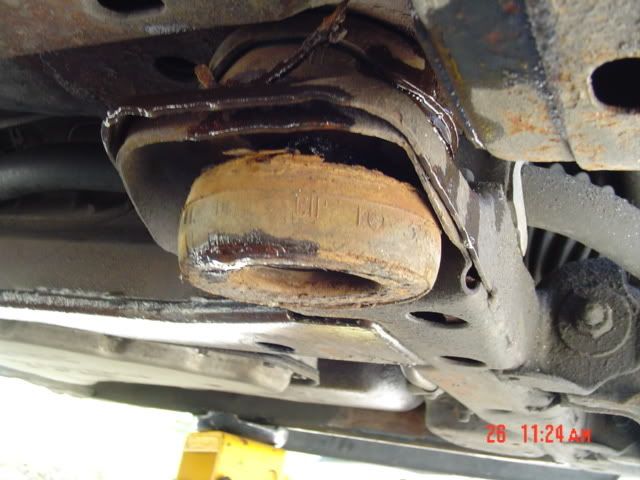
00009 -- Engine Cradle Corrosion
1990-93 W Model Vehicles
Located in the High Corrosion Provinces of Newfoundland, Nova Scotia, Prince Edward Island and New Brunswick
Condition
General Motors has decided that a defect which relates to motor vehicle safety exists in certain 1990-93 W model vehicles located in Newfoundland, New Brunswick, Nova Scotia and Prince Edward Island where exposure to moisture and salt can cause extreme levels of corrosion. Some of these vehicles exhibit a condition in which corrosion has caused loss of metal thickness at or near the engine cradle mounts. If sufficient metal thickness is lost, one or both of the front retainer and/or mounts may pull through, or the cradle may fracture forward of the rear mounts. If failures occur at both front or both rear locations, movement of the cradle can cause separation of the steering intermediate shaft. If this happens while the vehicle is moving, a crash could result without prior warning.
Correction
Dealers are to inspect the cradle assembly and install reinforcement plates. In vehicles where there is sufficient remaining metal thickness at the cradle mounting locations, a new cradle assembly will be installed.
Important
Cradle replacement will require DSM approval before repairs.
Where the engine cradle replacement repair costs may exceed the current fair market value of the vehicle, consult with your District Service Manager before proceeding.
It may be appropriate to assist the customer in purchasing or leasing a new or used General Motors vehicle. The offer of assistance must not exceed the fair market value of an identical model vehicle in similar condition but not requiring the engine cradle repair or the value of the repair, whichever is less. Licensing, sales tax, etc., would be customer responsibility.
Due to the age of the vehicles involved, published used vehicle value guides may not provide fair market values. It may be necessary to contact wholesalers or survey prices in your local market.
In very unusual circumstances, where the customer insists they are unable to afford any of the alternatives offered, a cash payment for their vehicle may be appropriate. Note: The customer is to sign a release.
Any vehicle purchased from the customers through the assistance outlined above must be scrapped in accordance with local practice so that it cannot be put back in service.
If the customer chooses to decline the fair market value offer, they should be advised that their vehicle is unfit for service and the Motor Vehicle Registrar will be notified by the Dealership.
Vehicles Involved
Involved are certain 1990-93 W model vehicles built within these VIN breakpoints:
Important
VEHICLES WHICH WARRANTY RECORDS INDICATE WERE PREVIOUSLY REPAIRED UNDER WARRANTY WITH NEW DESIGN CRADLES, P/N 12369168, ARE NOT INCLUDED IN THIS CAMPAIGN.
Year
Division
Model
Plant
From
Through
1990
Chevrolet
Lumina
Oshawa #2
L1159277
L1199198
1990
Chevrolet
Lumina
Oshawa #1
L9100281
L9317952
1991
Chevrolet
Lumina
Oshawa #1
M9100622
M9263327
1992
Chevrolet
Lumina
Oshawa #1
N9101166
N9288235
1993
Chevrolet
Lumina
Oshawa #1
P9100014
P9267779
1990
Pontiac
Grand Prix
Fairfax
LF201888
LF327802
1991
Pontiac
Grand Prix
Fairfax
MF200169
MF300893
1992
Pontiac
Grand Prix
Fairfax
NF201605
NF319317
1993
Pontiac
Grand Prix
Fairfax
PF200040
PF311143
1990
Buick
Regal
Oshawa #2
L1400896
L1456807
1991
Buick
Regal
Oshawa #2
M1402953
M1913768
1992
Buick
Regal
Oshawa #2
N1401321
N1514649
1993
Buick
Regal
Oshawa #2
P1400060
P1499102
1990
Oldsmobile
Cutlass Supreme
Doraville
LD300398
LD410550
1991
Oldsmobile
Cutlass Supreme
Doraville
MD300204
MD399797
1992
Oldsmobile
Cutlass Supreme
Doraville
ND302295
ND391772
1993
Oldsmobile
Cutlass Supreme
Doraville
PD300259
PD382693
Important
Dealers should confirm vehicle eligibility through GM Access Screen (Canada only) before beginning campaign repairs. [Not all vehicles within the above breakpoints may be involved.]
Involved vehicles have been identified by Vehicle Identification Number. Computer listings containing the complete Vehicle Identification Number, customer name and address data have been prepared, and are being furnished to involved dealers with the campaign bulletin. The customer name and address data furnished will enable dealers to follow-up with customers involved in this campaign. Any dealer not receiving a computer listing with the campaign bulletin has no involved vehicles currently assigned.
These dealer listings may contain customer names and addresses obtained from Motor Vehicle Registration Records. The use of such motor vehicle registration data for any other purpose is a violation of law in several states/provinces/countries. Accordingly, you are urged to limit the use of this listing to the follow-up necessary to complete this campaign.
Parts Information
Parts required to complete this campaign are to be obtained from General Motors Service Parts Operations (GMSPO). Please refer to your "involved vehicles listing" before ordering parts. Normal orders should be placed on a DRO=Daily Replenishment Order. In an emergency situation, parts should be ordered on a CSO=Customer Special Order.
Parts Table for Frame Corrosion Kits Part Number
Description
Qty/ Vehicle
88880032
Reinforcement Kit, Frame Front
1
12346501
Coating, Anti-corrosion (½ can per corrosion kit)
½ can
Parts Table for Drivetrain & Front Suspension Frame Assembly Part Number
Description
Qty/ Vehicle
12369168
Frame Kit, Drivetrain & Front Suspension Frame Assembly (Incl Instr Sheet)
1
10220561
Bolt, Frame (4 per frame)
4
10139080
Retainer, Frame Insulator
2
14087853
Spacer, Frame Insulator
2
14088025
Insulator, Asm, Frame Upper Front
2
14088026
Insulator, Asm, Frame Lower Front
2
10203413
Retainer, Frame Insulator
2
14088027
Insulator Asm, Upper Rear
2
14088028
Insulator Asm, Lower Rear
2
14087857
Spacer, Frame Insulator
2
26025653
Hose Asm, Power Steering Gear Inlet (V6 eng)
1
26028157
Hose, Power Steering Fluid Reservoir Inlet (V6 eng)
1
26046582
Pipe Asm, Power Steering Fluid Cooling (V6 eng)
1
Service Procedure
Important
The frame/cradle assembly must be replaced if any of the following conditions are found before or while performing this service:
NOTE: Prior DSM authorization is required before proceeding to replace a cradle.
Plate(s) welded or obvious repairs performed to any area of the frame/cradle assembly.
Part(s) broken off or missing due to rust perforation or mechanical damage.
Perforation(s) or crack(s) around the front mount area which extend within 32 mm (1-¼ in) of the leading edge of the cradle or rearward more than 120 mm (4-¾ in) of the leading edge of the cradle.
Perforation(s) or crack(s) in the area between the rear body mount and the stabilizer shaft attachment.
Crack(s) under the stabilizer shaft clamp attachment.
Perforation(s) or crack(s) on the crossmember(s) side rail(s) or bracket(s) not specifically mentioned above.
Front Cradle Reinforcements Procedure/Rear Cradle Reinforcements Procedure
The rear cradle reinforcements procedure begins with Step 18.
Raise and suitably support the vehicle.
Remove both front wheel and tire assemblies.
Caution
Failure to disconnect the intermediate shaft from the rack and pinion steering gear shaft can result in damage to the steering gear and/or intermediate shaft. This damage can cause/result in an accident and possible personal injury.
Disconnect the intermediate shaft at the steering gear stub shaft.
Support the front of the frame assembly.
Remove and discard both the front frame/cradle mount bolts.
Lower the front of the frame/cradle assembly approximately 100 mm (4 in).
Remove and discard both the right and the left front frame/cradle mount assemblies.
Scrape and wire brush the frame/cradle assembly on the upper and the lower surfaces that are contacted by the mounts.
Measure and record the location of the 32 mm (1-¼ in) alignment pin access hole in the underside of the right front lower frame horn surface. Transfer and mark this location to the left front lower frame surface. Using a 1-¼ inch (32 mm) hole saw, cut a hole through the left front lower frame horn surface similar to the alignment pin access hole found in the right front lower frame horn surface.
FIGURE Front Cradle Reinforcement (Left Side Shown-Right Side Similar)(c)
Important
The lower front insulators (7) have been pressed into the front lower reinforcement plates (5) to ensure proper fit and will require disassembly prior to installation. Identify and keep together parts that have been disassembled from one another for assembly purposes. The lower reinforcement plates are identified with the letter "R" or "L" indicating right or left side, respectively.
Position the left front reinforcement plate (5) with the insulator removed, inside the left front frame horn. Install the front lower insulator (7) and visually align the insulator/reinforcement plate assembly with the cage nut in the vehicle underbody. While holding the insulator/reinforcement plate assembly in position, mark the frame at the centre of the small hole in the reinforcement plate. Remove the front lower insulator (7) and reinforcement plate (5).
Working through the access hole previously cut in the lower surface of the frame horn, drill a 13 mm (½ in) hole at the location marked in the previous step.
Wipe and blow off the areas that were scraped or wire brushed, removing any foreign material from the front frame horns.
Apply anti-corrosion compound, P/N 12346501, to the right front mount areas from the bend in the horn forward, on both the upper and lower surfaces and the inside section of the frame/cradle assembly.
Install the front reinforcement plates (4 & 5), the bolts (3), and hand start the nuts (6) at both front mount locations as shown in the illustration.
Important
Lubricate the insulators with rubber lube, P/N 12345884 or the equivalent, at the time of installation.
Install the front lower insulators (7), the upper insulators (2) and the spacers (1) at both front mount locations.
Raise the frame/cradle assembly up to the underbody.
Install the front mount retainers (8) and hand start the front frame/cradle mount bolts (9). Tighten
Tighten the reinforcement plate nuts (6) to 85 N·m (62 lb ft).
Tighten the frame/cradle mount bolts (1) to 110 N·m (82 lb ft) and ensure that the lower insulators are seated to the reinforcement plates.
Support the rear of the frame/cradle assembly.
Remove and discard both the rear frame/cradle mount bolts.
Lower the rear of the frame/cradle assembly 40 mm (1-½ in).
Remove the discard both the right and the left rear frame/cradle mount assemblies.
Remove and discard the fasteners securing the stabilizer bar insulators and the clamps to the frame/cradle assembly.
Scrape and wire brush the frame/cradle assembly on the upper and the lower surfaces that are contacted by the mounts, the stabilizer shaft attachments and the waterfall area on the sides of the assembly.
Important
Excessive weld and weld flash must be removed from the area where the rear crossmember meets the side rail to ensure that the rear reinforcement plates lay flat on the frame/cradle assembly.
Inspect and remove any weld flash or excessive weld from the frame/cradle assembly where the rear crossmember is welded to the frame/cradle side rails.
Wipe and blow off the areas that were scraped or wire brushed in order to remove any foreign material.
Apply anti-corrosion compound, P/N 12346501, to the rear mount, the waterfall and the stabilizer shaft bracket surfaces and the inside section of the frame/cradle assembly.
FIGURE Rear Cradle Reinforcement (Left Side Shown-Right Side Similar)(Right Side Reinforcement Plate Has Different Contour Than Left Side)(c)
Position the right and the left rear reinforcement plates (7) on the top surface of the rear frame horns as shown in the illustration.
Install the stabilizer shaft stud brackets (3) up through the frame/cradle assembly, the rear reinforcement plates (7), the stabilizer shaft, the insulator clamps (2) and hand start the stud bracket nuts (1). Tighten
Tighten the stabilizer shaft stud bracket nuts (1) to 60 N·m (45 lb ft).
Important
Lubricate the insulators with rubber lube, P/N 12345884 or the equivalent, at the time of installation.
Install the rear lower insulators (6), the upper insulators (8), and the spacers (9) at both rear mount locations.
Raise the rear of the frame/cradle assembly up to the underbody.
Install the rear mount retainers (5) and hand start the rear frame/cradle mount bolts (4). Tighten
Tighten the rear frame/cradle mount bolts (4) to 110 N·m (82 lb ft).
Connect the intermediate shaft at the steering gear stub shaft. Tighten
Tighten the pinch bolt to 47 N·m (35 lb ft).
Install the front wheel and tire assemblies. Tighten
Tighten the wheel nuts to 140 N·m (103 lb ft) using a torque wrench or appropriate torque limiting socket. Tighten the wheel nuts using a "star pattern."
Lower the vehicle.
Set the alignment to specification.
Install the GM Campaign Identification Label.
Campaign Identification Label
Place a Campaign Identification Label on each vehicle corrected in accordance with the instructions outlined in this Product Campaign Bulletin. Each label provides a space to include the campaign number and the five (5) digit dealer code of the dealer performing the campaign service. This information may be inserted with a typewriter or a ball point pen.
Put the Campaign Identification Label on a clean and dry surface of the radiator core support in an area that will be visible to people servicing the vehicle. Additional Campaign Identification Labels for Canadian dealers can be obtained from DGN by calling 1-800-668-5539 (Monday-Friday, 8:00 am to 5:00 pm EST). Ask for Item Number GMP 91 when ordering.
Claim Information
Submit a Product Campaign Claim with the information indicated below:
Repair Performed
Part Count
Part No.
Parts Allow
CC-FC
Labour Op
Labour Hours*
Net Item
Install cradle corrosion kit
1
88880032
**
MA-96
V0466
1.4
***
Install new cradle assembly (includes alignment)
(Requires prior approval by District Service Manager)
21
12369168
**
MA-96
V0467
4.0
***
Inspect and offer customer trade assistance
--
--
--
MA-96
V0518
0.3
****
* -- For Campaign Administrative Allowance, add 0.1 hours to the "Labour Hours".
** -- The "Parts Allowance" should be the sum total of the current GMSPO Dealer Net price plus applicable Mark-Up for cradle reinforcement kits or cradle assemblies needed to complete the repair.
*** -- The amount identified in the "Net Item" column should represent the sum total of the Current GMSPO Net Price plus applicable Mark-Up for anti-corrosion compound and rubber lube needed to perform the required repairs.
**** -- The amount of the trade assistance offer accepted by the customer.
Refer to the General Motors WINS Claims Processing Manual for details on Product Campaign Claim Submission.
Reimbursement
Customer requests for reimbursement of previously paid repairs to correct cradle corrosion are to be submitted by April 30, 2001.
Consideration for reimbursement will be allowed only if genuine General Motors parts were used. The amount to be reimbursed will be limited to the amount the repair would have cost if completed by an authorized General Motors dealer.
Owner reimbursement may not be allowed if obvious previous repairs inappropriately performed to any area of the frame/cradle assembly.
When a customer requests reimbursement, they must provide the following:
Proof of ownership at the time of the repair.
The original paid receipt confirming the amount of unreimbursed repair expense(s), a description of the repair, and the person or entity performing the repair.
NOTE: WHEN REIMBURSING PREVIOUS REPAIRS, THE CUSTOMER IS TO SIGN A RELEASE.
Claims for customer reimbursement on previously paid repairs are to be submitted as required by WINS.
Important
Refer to the GM Service Policies and Procedures Manual, section 1.6.2, for specific procedures regarding customer reimbursement verification.
Customer Notification
Customers will be notified of this campaign on their vehicles by General Motors (see copy of customer letter included with this bulletin).
Dealer Campaign Responsibility
All unsold new vehicles in dealers' possession and subject to this campaign MUST be held and inspected/repaired per the service procedure of this campaign bulletin BEFORE customers take possession of these vehicles.
Dealers are to service all vehicles subject to this campaign at no charge to customers, regardless of mileage, age of vehicle, or ownership, from this time forward.
Customers who have recently purchased vehicles sold from your vehicle inventory, and for which there is no customer information indicated on the dealer listing, are to be contacted by the dealer. Arrangements are to be made to make the required correction according to the instructions contained in this bulletin. This could be done by mailing to such customers a copy of the customer letter accompanying this bulletin. Campaign follow-up cards should not be used for this purpose, since the customer may not as yet have received the notification letter.
In summary, whenever a vehicle subject to this campaign enters your vehicle inventory, or is in your dealership for service in the future, please take the steps necessary to be sure the campaign correction has been made before selling or releasing the vehicle.
May 2000
Dear General Motors Customer:
General Motors has decided that a defect which relates to motor vehicle safety exists in certain 1990-93 W vehicles. Some of these vehicles operating in high corrosion provinces of Newfoundland, Nova Scotia, Prince Edward Island and New Brunswick, exhibit a condition in which corrosion has caused loss of metal thickness at or near the engine cradle mounts. If sufficient metal thickness is lost, one or both of the front retainer and/or mounts may pull through, or the cradle may fracture forward of the rear mounts. If failures occur at both front or both rear locations, movement of the cradle can cause separation of the steering intermediate shaft. If this happens while the vehicle is moving, a crash could result without prior warning.
Your GM dealer will inspect the cradle assembly and install reinforcement plates. In vehicles where there is sufficient remaining metal thickness at the cradle mounting locations, a new cradle assembly will be installed. This service will be performed for you at no charge .
You may be contacted by a dealer other than the dealer who sold or is currently servicing your vehicle. Please be advised that you may take your vehicle to the General Motors dealership of your choice to have the recall service work completed. Please contact your dealer as soon as possible to arrange a service date.
If parts are required, ask your dealer for details regarding their availability. If parts are not in stock, they can be ordered before scheduling your service date.
This letter identifies your vehicle. Presentation of this letter to your dealer will assist their Service personnel in completing the necessary correction to your vehicle in the shortest possible time.
We are sorry to cause you this inconvenience; however, we have taken this action in the interest of your continued satisfaction with our products.
Customer Support Department
General Motors of Canada Limited


 Previous Topic
 Index
Index