Audio Upgrade
This
is a description of the audio modifications that John Tsimaras
made to his '98 Grand Prix sedan. He also wrote this page.
It
is presented here to provide information to other people looking
for similar upgrades. There are some pictures here, but they were
taken after the fact, not during the actual installation. You may
find this long-winded, or maybe you're only interested in a few
sections. This is also my first web page, so if it violates some
conventions, please forgive me.
Basically,
this upgrade fulfilled my simple requirements:
- Keep the stock head unit -
I like gadgets so I did not want to lose the steering
wheel controls and HUD integration. Yes, I'm aware of the
Soundgate adapter that will allow Sonys to be used with
the Pontiac's steering wheel controls, but you still lose
the HUD. I also do not care for the fact that most
aftermarket head units don't visually fit in with the
rest of the controls in the dash. And lastly, the stock
unit is quite good in sound quality.
- Wanted some power in the
sound, but NOT ear-shattering loudness - I don't want to
abuse my hearing.
- Wanted to improve on the
weakest part of the system, which in my opinion is the
stock speakers.
- Add some needed bass to
the system.
I
thought about it for a while and consulted with a few people as
to go about it. Mike Napurano responded to a couple of questions
that I posted regarding upgrading the rear speakers. I didn't
agree with him at the time, but by the time I finished my
research I discovered that his advice to remove the 6X9s
altogether was right on the money. Thanks Mike!
The
following is a listing of the components that I added, along with
some supplies:
- MB Quart separates for the
front doors (Model 215.03 CX). These use 5 1/4"
woofers and 3/4" tweeters. (Local retail)
- Infinity Kappa 4"
coax speakers (Model 42i) for the rear deck.
(Crutchfield)
- Soundstream Reference 405s
5-channel amplifier. (Local retail)
- JL Audio 8.1 Micro Sub.
The driver is only 8", but I really like the sound
plus it's small. (Local retail)
- Dynamat (Crutchfield)
- Charcoal carpet
(Crutchfield)
- Amp wiring kit (Local
retail)
- Speaker wire. 16 ga. for
front and rear, 12 ga. for sub (Crutchfield)
- AudioLink Level converters
(Crutchfield)
- RCA wires 3 feet in length
to go between the level converters and amp (Crutchfield)
- Door panel fasteners (Part
number 10153057 at Pontiac Dealer)
- Miscellaneous connectors,
and nylon ties.
Wiring Schematics
So what did I do? I replaced the
stock 5 1/4" and tweeter components in the front doors. I
also replaced the rear 4" drivers, and as already mentioned,
removed the rear 6X9s altogether and added a sub. I also added a
5-channel amplifier to drive the speakers and the sub. I also
removed (electrically) the stock amplifier for the 6X9s that
aren't there anyway. The reason I did that is that I did not want
to have this unit's inputs wired in parallel with my new amp's
inputs. I didn't want it to lower the impedance that the stock
head unit sees and I was also concerned about it feeding anything
back to the head unit and the new amp. Before the installation, I
decided how I was going to wire the system. The following two
figures show the stock stereo wiring, and how I decided to wire
my system. The stock wiring was derived from the Service manual.
I strongly advise anyone thinking of doing any significant work
on this (or any) car to get the service manual and spend some
time planning the mods. This makes for fewer surprises. 
The
new system wiring is nothing out of the ordinary. It's about as
typical as it gets. 
If
anyone's interested, I found the following pages in Volume 1 of
the '98 Service manual were very helpful: 8A-150-0, 8A-150-3,
8A-201-36, 8A-203-0, 8C-16, 9A-15, 10-6-1, 10-6-11, 10-6-24,
10-10-17, 10-10-22.
Before
starting the job, I decided that the line converters and the amp
would go in the trunk. I also decided that I would get the signal
for the front line converter from under the dash, and the rear
signal right from the full range 4" speaker connectors in
the trunk for convenience. I also decided to do all the tearing
apart first, to get it out of the way so that I could concentrate
on the installation once I got started. I began in the trunk.
First, roll up and remove the removable carpet in the trunk. I
also pulled out the fiberglass spare tire cover. There are some
voids under it, and I didn't want to crack it by placing weight
in the wrong place. I placed a scrap piece of 1/4" plywood
in it's place to cover the hole. I knew that I'd be spending a
lot of time in the trunk.
Removing
Rear Seat
Next, I pulled out the rear seat.
You have to take the seat bottom out first. There are two nylon
pulls under it's front edge. They release the front of the seat.
I found that they will release easier if you place some weight on
the seat directly over them as you pull on them firmly but
steadily. Don't tug on them sharply, or they may break. Once you
feel that they've released pull up on the seat's front. You can
then slide the seat bottom forward and remove it from the car.
Once the seat bottom is removed, the seat-back comes next. The
seat-back is held in place with four nuts. Two smaller ones about
8 to 12 inches from the side doors, and two large ones near the
middle that also hold the inner seat belts in. Take note of the
orientation of the seat belts before you pull them out so you can
put them back in the same way. Once all the nuts and the two belt
assemblies are removed you can pull out on the bottom of the
seat-back and move the entire seat-back up to release four wire
hooks that anchor the top. I struggled with it for a while,
because the bottom anchors kept slipping back over the protruding
bolt studs as I pulled up. What helped was the following: Pull
out a little on the seat-back until it clears the bolts, and then
slip the nuts underneath and thread them backwards on the bolts.
The nuts used have washers attached to them, so what I mean by
backwards is, have the washers facing out. So when the nuts are
in backward, behind the seat, they will prevent it from going
back over the studs. You can then concentrate on yanking up
without worrying about the seat getting hung up on the bolts.
This also makes sure that you don't misplace the nuts until you
need them when you put the seat back in. Once the seat is out,
the rear deck cover comes next. There are two nylon fasteners on
it's front portion that need to be removed. Fortunately, these
are not the self-destructing type. Once the fasteners are out,
the deck cover can be coached out. You don't need to remove the
lower side trim on either side to remove it.
Removing
Rear Speakers
With the rear deck cover out of
the way, you will see that the speakers are not mounted directly
to the metal deck. Instead, they are attached to plastic
stand-offs or platforms that hold them about two inches above the
metal deck. Unscrew the speakers, but leave the plastic platforms
in place. You won't really need the larger ones used for the
6x9s, but you will need the smaller ones to attach the new
4" drivers to.
Removing
Door Panels
If you need a second source of
information on removing the door panels, there is another document
available. Otherwise, read here:
Next,
pull out the front door panels. Start by removing the plastic
trim caps that cover two bolts under each door's pull handle. The
bolts are torx. I used a hex bit of the right size that attaches
to my screw gun to take them out. By the time I finished the job
I misplaced the bit and had to improvise in order to put the
bolts back in. I found that the flat blade on one of my
electrician's screwdrivers was the perfect size to fit in the
torx recess. Once the bolts are out, you can start yanking on the
edges of the door panels to remove them. As many have said, the
nylon fasteners that they used on this car are self-destructing.
I was somewhat prepared as I went to a dealer ahead of time and
bought a bag of them (10). That's all he had. These are much
better than the original ones. The part number is 10153057.
Unfortunately, I found out later that each door panel requires
eleven of these things, and I only had 10. Before you can pull
the door door panels off altogether, you need to disconnect some
wires. First disconnect the connector that goes the courtesy
light near the back of the door. That's relatively easy. The
tweeter connector is also pretty easy. More difficult are the
multiple connectors that go to the window and power lock and
rear-view mirror controls. The manual says to push forward on the
entire control panel, and to pull up on its back end. I tried
this, but it didn't budge, and I didn't want to take a chance on
marring the door panel or breaking the control panel. Instead, I
reached under the door panel, and pushed on the locking tab that
held the control panel in place. Much easier. Once the control
panel is up and loose, disconnect all the electrical connectors
from it and put the control panel itself in a safe place. Once
this is done, you can just pull away the door panel and put it in
a safe place.
Removing
Carpet retainers
This was the easiest part of the
job. The front retainers are each held in place with four screws.
Three on the bottom (about 2") and one in the front at the
top. The rear carpet retainers look easy enough. There's two
screws holding each of them in place, but they're actually one
piece with the center pillar trim cover. The manual says that if
you pull on the trim covers they will release, but mine didn't
want to budge. So I left them in place. I just pulled the longer
carpet retaining portion out of the way.
Removing
Lower Instrument Panel Covers
On either side of the instrument
panel, on the bottom, there's a felt cover that covers up wiring
and stuff. These are held in place with those nylon fasteners.
The good re-useable type. If you pull these fasteners out, the
panels will drop out. Twist the little lights off from each and
get them out of the way. Save the fasteners for reuse later.
Making and installing amp
supporting panels
Before getting started I made two
panels out of 3/4" plywood. These go in the trunk, and
attach to the steel framework behind the rear seat-back. I used
one panel (right) to attach the amp. I made the other one (left)
so that it would look symmetrical. I later attached the line
level converters to it. For appearance, I covered them with
charcoal colored carpeting that I ordered from Crutchfield.
Another benefit to these panels, is that they cover up the foam
backing that you see against the seat-back in the trunk. I think
that looks kinda cheezy. The diagram below shows the dimensions
and outlines of the plywood panels. 
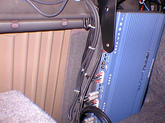
In making the panels, it was
necessary to cut out a rectangular section at the top innermost
corner of each panel. This leaves the necessary clearance
required for the "hooks" that hold the top of the
seat-back in place. If you look at the picture below, you can see
the two panels installed on either side of the pass-through
opening. Just above and to the right of the two line converters
(on the left panel) you can see one of the U-shaped hooks that
hold the seat-back in place. Without the cutouts you can't get
the seat back in. This photo was taken after the installation was
complete. Here, the sub was removed from its bracket in order to
show what the panels look like installed and the cut-outs
required for the hooks. Normally the sub fires into the
pass-through. The coil of wire that you see feeds the sub. I left
it long so that If I ever need to remove the sub and throw it in
the back seat, I won't have to disconnect the wire.
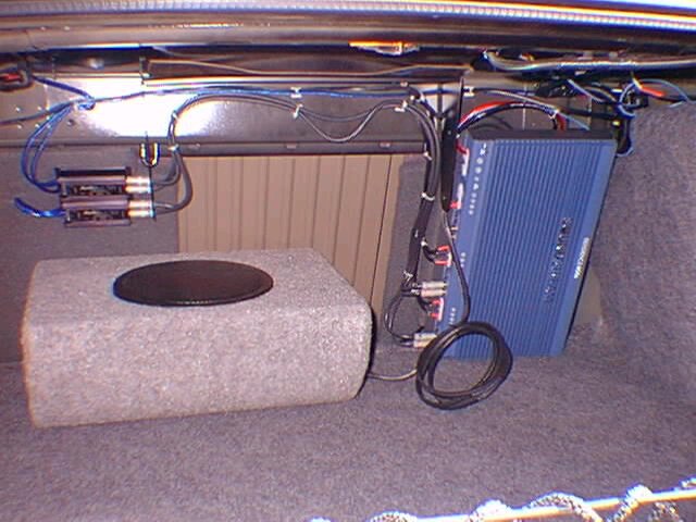
Looking
at the wiring above the amp, I'm compelled to go back out and
dress them up a bit better. From this angle it looks like crap,
although you usually can't see them. Here's another angle. In
this picture the cut-out required to accommodate the U-shaped
hook is easier to see. The black bracket at the top of the
picture is the sub's support.
Once the panels
are cut and carpeted (I used spray adhesive that I bought from a
local crafts shop) they are screwed in place from the passenger
compartment. The way that the car's frame is, you can only attach
the panels at the top edge, and along the outermost side edge of
the panel. There is no sheet metal surrounding the pass-through
opening. However the panels are small enough, that at 3/4"
thickness and secured along the entire top and one side, they are
fairly sturdy. After all, they're only holding up an amplifier.
Once
the panels were installed, the next step was to attach a platform
for the amplifier. What's that you ask? Well, the amp I chose was
about 1/2" too long for the place I selected. With the amp
resting on the trunk floor, the top of it did not clear this
ledge that's just below the rear deck. You can actually see the
ledge in the picture above The U-shaped seat attachment
hook comes through the bottom of this ledge. So I built (and
carpeted) a platform that would raise the sub off the plywood
panel enough so that it would clear the ledge. I tried to find an
angle that I could take a picture from to show the platform, but
I couldn't find one. Not without removing the amp. So this
drawing may help.
I assembled the
platform using glue and screws. When complete, I screwed the
platform onto the passenger side panel. At this point the
installation was ready for the amp, but I waited until all the
wires were run into the trunk before mounting the amp to its
platform. The reason for this is that some of the wiring enters
the trunk directly behind the amplifier. Drilling holes through
the plywood panel and pulling the wires through is easier without
the amp in place.
Running
speaker wires
The level
converters were to be mounted in the trunk with the amplifier. I
had already decided for convenience, that I would get the front
speaker signals from under the dash by tapping into the stock
amplifier's connector. As far as the rear speaker signals, by far
the easiest thing to do was to get them right from the connectors
that originally fed the original 4" full range speakers
mounted in the rear deck.
I tackled the
front wiring first. Since the signal for the front speakers were
coming from under the dash, it was required that four speaker
wires be run. Two speaker wires will take the audio signals from
the head-unit to the level converters (I call these input wires),
and two wires will take the output signal from the amp to the
front speakers (output wires). I also used different color wires
for input and output, to make my life a little easier. I helped
that I just happened to have two different colors of 16 ga.
wire. I used blue for input wires and black for output
wires consistently. I guess I'm a stickler for consistency. I
also think that this combination of colors sounds better
<G>. Make sure that you have enough wire for the job,
because it's deceiving. You will need a lot of wire, as I used a
total of about 75 feet.
I also decided
before beginning that I would run all speaker wires down the left
side of the car, and the power cable that goes to the battery
down the right. This will minimize noise pickup on the speaker
wires.
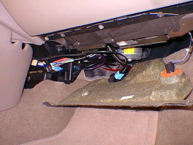
For the input
signals, the most convenient place is to tap them right from the
stock amplifier just below the glove compartment. First,
disconnect the connector from the amp. If you look at the picture
below, find the yellow sticker. Now, if you look just above the
sticker, that's the amp partly exposed. The connector plugs into
the left side of the amp. Once the connector is free, I cut four
wires (there are other ways to tap into the signals, but I was
not looking to make a career of this. It is easy enough to revert
to the original connections if I ever want to.) You can see the
connector with the crimped connectors dangling towards the left,
just forward of the center console. The wires to cut are:
- TAN in
position A1 - Left Front positive
- GRAY in
position B1 - Left Front negative
- LIGHT GREEN
in position A2 - Right Front positive
- DARK GREEN
in position B2 - Right Front negative
Be
careful, there's another dark green wire in that connector in
position B11. That actually goes to the right rear 6X9. You don't
want that wire.
Before any
crimping, I pre-cut two lengths of wire that would carry these
signals to the trunk. It's a good idea to wrap some tape around
each end of each wire and label them so that you won't confuse
left, right, front, and rear. Once that was done, I crimped the
new wires to the four wires that I cut from the amp connector.
Then run the wires neatly under the dash to the parking brake
area. From there you can start tucking the wires neatly where the
carpet retainer was removed. I was concerned that it may be very
tight to run four speaker wires (2 input, 2 output) under the
carpet retainer. I found out that it was pretty easy. You just
need to be neat about it. Run the wires parallel and flat,
stacked on top and next to each other. Don't twist them or cross
them, and there will be plenty of room. When you remove the
carpet retainers you will see a vinyl flap that runs the entire
length of the door sill. There's enough room under this flap. If
you keep the wires under this flap, you also don't have to worry
about the screws cutting them later when you put everything back
together. You may remember that I wasn't able to yank the center
pillar lower trip piece off. This really wasn't a problem. It's
flexible enough that the wires can be pushed up under it. Then
continuing past the rear door sills was just as easy. When I got
to the rear lower trim (the part next to the seat), I was able to
pull that away from the sheet metal. It's held in place with
metal re-usable retainers. Pass the wires under this trim piece,
and behind the outboard retractable seat belts. It's pretty easy.
Once there, I drilled through the driver-side plywood panel and
passed the wires through. If you look at the first photograph on
this page, you can see the blue wires coming out of the gray
panel and right into one of the level converters.
The rear speaker
input wires were a piece of cake. Since I bought the 4"
Infinitys at Crutchfield, they sent me adapters that plug into
the stock GM speaker connectors. I took these adapters and cut
off the slide connectors that are used to connect to the speaker
itself. I then crimped new wire to the adapters, and ran that
wire to the other line converter. When you crimp the new wire
onto the adapter, make sure you keep the following convention:
- BROWN -
Left rear 4" speaker positive
- YELLOW -
Left rear 4" speaker negative
- DARK BLUE -
Right rear 4" speaker positive
- LIGHT BLUE
- Right rear 4" speaker negative
Now that the
input wiring is done, it's time for the output wiring. These
wires will go from the amp outputs to the new speakers. Again,
pre-cut some lengths and label them as before. I ran them from
the amplifier area, through the passenger side panel, across the
rear seat area, and over to the driver side of the car. I ran
these wires the same as the others over to the parking brake
area. One wire will go into the left door, and the other will go
under the dash, over to the right door. No problem, right? NOT!
It's easy enough to get the wires to the vicinity of the doors,
but passing them through the rubber boot into the actual door
proved interesting. The first one took me about one hour. The
second took five minutes, because I learned the trick. What's the
trick? Well you have to disconnect the rubber boot from both
sides (the door and the frame), and compress it. You can then
pass the speaker wires through, one step at a time. First through
the frame, pull all the excess wire out. Then thread it through
the boot, and pull all the excess wire out. Then pass it through
the door opening and finally through the speaker opening. Then go
back and push the boot ends back in place.
This assumes
that the crossovers for the front woofers/tweeters will be
mounted in the door, as I did. If one decides to put the
crossovers somewhere else, like under the dash, this will be a
little different. You will need to run two speaker of wires
through each boot.
The output wires
for the rear 4" speakers was trivial. Just run wire from the
amp to the openings under the rear deck for the 4" speakers.
Installing
Front Woofers and Crossovers in Doors
The woofers
were straight forward enough. I first removed the plastic speaker
holders (what do you call those things anyway?). I then put a
piece of dynamat over each opening (maybe 8" x 12",
from memory). I took the cut-out section of dynamat from the
speaker opening in the door and stuck it to the inside of the
door skin, just opposite the speaker itself. There was already a
pad attached there from the factory, so I just put the dynamat on
top. When and if you use dynamat, make sure that it stops short
of where the interior door panel wants to go. Otherwise, the
panel will not sit flush against the door. Once the dynamat was
done, put the speaker holder things back in. I also like to put
electrical tape over the raw metal edge of the opening so that
the wires will not abrade.
I had decided
that the crossovers would go in the doors. There is room for them
behind a bulge near the bottom rear corner of each front door.
Under the courtesy light. I used some pretty sticky pre-formed
silicone bead to hold the crossovers in place. With the
crossovers there, you need to pass two wires through the speaker
openings. One is the main wire from the amp (that came from the
trunk) that will go to the crossover input, and the other is the
crossover output that will drive the woofer. If you look at the
plastic molded speaker holder, there is an indent under the
speaker for this, but there's room for one wire only. In the
stock scheme, the wires that fed the tweeter passed through this
indent. Anyway, I drilled a hole at the bottom of these plastic
things, and ran the amp output wire through this hole. This wire
gets attached to the crossover input. I then ran another wire
from the crossover's woofer output and attached it to the woofer.
Place the woofer in this plastic holder and let the wire sit in
the pre-formed indent. Otherwise, the speaker won't sit flush.
Next connect another wire to the crossover's tweeter output. The
other end of this wire should be long enough to reach the
tweeter, with some slack. It should also have connectors that can
later mate with the tweeters. Take some time and dress up the
wires. Tie them together and out of the way so they won't get
damaged when the door panel is replaced later.
Installing
Tweeters in the Door Panels
First remove
the old tweeters from the sail panels in the door panels. There
are three locking tabs that hold each tweeter in place. Besides
that, there are two positioning tabs that define the orientation
of the tweeters. There was no way for me to retrofit these five
plastic tabs to hold my new tweeters in place. I broke all five
off, and was left with a flat plastic ring that the tweeter could
sit against. I tacked each tweeter in place on this ring using
hot melt glue temporarily, until I tested them later.
Power
Connections to the Amp
At this
point, I wanted to start testing my work so that I could start
closing things up, so the power connections for the amp came
next. First of all, the Grand Prix has a remote 12V power point
that is excellent for running a power cable. The picture below
shows this point.
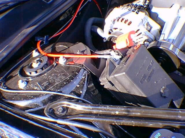
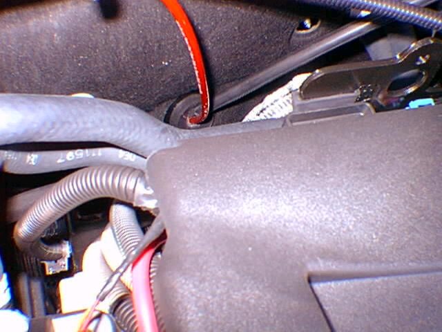
The
red cable is the power cable. Note the fuse housing on the power
cable right by the rear strut tower bolt. You will also note that
the power cable is wrapped around an existing cable. I did this
to make sure that it would not touch the hot engine. One of these
days I will dress it with wire loom. Connecting to this power
point was the easy part (But don't do it just yet. You'll want to
run it to the trunk first or you could have some pretty sparks.
It's best if you attach the other side first, the ground cable,
and the remote turn-on lead before you attach the power lead to
battery). The not so easy part was finding a way to bring the
cable through the firewall. I found a soft rubber grommet
behind the engine where a cable was already going through. It
looked like a great place. It's shown in the picture below.
In trying to
push the cable through the rubber grommet, I discovered that
there is a rubber sound deadening membrane on the compartment
side of the firewall. So I couldn't push the cable through. I
took a long screwdriver, and gently <G> passed it through
the grommet, and then pushed it through the membrane. I left the
screwdriver in place to help me locate the new opening from
inside. Once I found it, I enlarged the hole a bit. Then it was
simply a matter of threading the cable through the grommet and
the opening in the rubber membrane on the inside. I would
recommend that you seal the area in the grommet where it was
violated <G> with some silicone. The picture above doesn't
show it, but I have since sealed the opening. Once the cable is
through to the inside cabin, it's an easy matter to run it down
the right side of the car to the amp in the trunk.
The ground wire
was much easier. I connected it to one of the screws that hold
the sub bracket to the bottom of the rear shelf.
The only wire
left to do before any testing was the remote power lead. This
wire turns on the amplifier when it receives a 12V turn-on
voltage. This is usually a much thinner wire than the power and
ground connections for the amp, since it draws very little
current. It's typically about 18 ga.
I have the UP3
stereo (CD in dash) with the rear-window antenna. The presence of
the rear-window antenna makes it very easy to get a turn-on
voltage for this lead. The wire to tap into is the yellow lead
that goes to the antenna amplifier. It turns out that the antenna
amp needs the same turn-on voltage to do it's job. The bonus is
that this lead is also hot when using the CD. (I cannot speak for
other stereos, or for cars with the mast antenna. If you don't
have the rear-window antenna, you may have to get a signal from
the instrument panel fuse block)
Anyway, where is
this wire? I took a picture and had intended to include it here,
but after looking at it I decided that it was hard to make out
and would probably add confusion. So I left the picture out. The
place to look is under the rear shelf, on the passenger side,
somewhere between the 4" speaker opening and the right-rear
strut tower. You will see a bundle of wires (portion of the rear
deck and trunk harness) that is taped over it's entire length
with black electrical tape. At one point the bundle splits and
most of the wires continue on under the deck, but a smaller
grouping separates and goes up into a hole (about 1" in
diameter) into the rear deck. It's easy to identify because one
of the wires that break off and passes through the hole is a much
thicker black coax lead. This is the antenna lead itself. One of
the wires accompanying this coax is yellow. Be careful, because
there's another yellow wire in the group of wires that do not
pass through the hole. MAKE SURE TO USE THE ONE THAT GOES THROUGH
THE HOLE. Now, there's only about a 2 inch section of it exposed,
so you may need to cut back some of the electrical tape that's
used to bundle the wires, just to have some working room. Tap
into this wire using your favorite means. I used one of those
T-connection connectors that I bought in an auto parts store. It
caused me some grief, but that's a story for another day.
Connect the RCA
wires between the level converters and the amp inputs, and you
can start your testing. At this point when you turn on the radio
the amp should also turn on, and you should get sound out of the
front door woofers. The tweeters should not be in at this point
yet. Make sure that the balance and fader controls aren't
crossed. If you labeled the speaker cables as you ran them there
shouldn't be a problem. You could also listen for the speakers
being out of phase. Out of phase speakers have a very distinctive
sound. Basically, there is no imaging as it's hard to localize
where a sound is coming from.
Installing
the Tweeters and door panels
At this
point the tweeters are tacked into the sail panels temporarily
(with hot melt glue), and the wires leading from the tweeters
should have connectors that will mate to the leads coming off the
crossovers. Pull the door panels over to the doors and connect
the tweeter connectors to the tweeter wires from the crossovers.
Turn on the stereo again and make sure that the tweeters work.
Once the tweeters were tested and they worked, I used some more
of that pre-formed silicone bead to secure them in place inside
of the sail panels. The hot-melt glue that was used to hold them
would likely fail in the summer as the interior gets real hot
when the car sits in the sun. Now I was ready to close up the
door panels.
I've mentioned
already that the nylon fasteners are not really re-useable. But I
only had 10 of the new ones to use between the two door panels.
So, I discarded the five sorriest looking fasteners from each
door panel. I then moved the fasteners around so that the new
ones were in the more "strategic" locations, like the
tops of the panels, the bottom corners, and one on the bottom
edge in the middle. Putting the door panel back in is pretty
easy. Just reverse the steps used for disassembly. First pass the
door release handle through the panel, align the panel in it's
general location, reach in and connect all electrical connections
(to the courtesy light, and to the switch control panel), and
push the panel back in place. Don't forget to put the torx screws
under the door pull back in, and the trim caps.
Installing
the rear 4 inch speakers
This is one
of the easiest steps. You need to run the speaker wires from the
amp outputs to the holes where the 4" speakers will go.
Connect the wires to the speakers and then mount the speakers to
the plastic platforms. Done! Now test the rear speakers as well.
Installing
the Sub
The sub that
I used was a breeze to install. The sub mounts to a steel bracket
that attaches to the rear deck from underneath. I actually
installed the bracket earlier, when I did the power connections.
I had decided to attach the ground cable to one of the sub
bracket mounting bolts, so I had to install the bracket before I
could power up the amp to start testing. There was no science
here, I just decided where the bracket goes and screwed it in
place with self-tapping sheet metal screws. Before I attached the
bracket however, I did cover a good portion of the bottom of the
deck with dynamat. I attached the wire to the sub (12 ga.), and
then the sub to the bracket. That's it!
It's worth
mentioning that my amplifier and configuration does not require a
separate input signal into the amplifier for the sub. The
amplifier generates the sub output signal internally from the
other 4 channels. (Another reason that I did not need to reuse
the stock amp.)
Finishing
Up!
Once I was
satisfied that everything worked, I put the carpet retainers back
in, vacuumed, put the rear-deck cover back on, and re-installed
the rear-seat and seat belts. Don't forget to go back in the
trunk and dress the wires up a bit for a neat appearance. Here's
what my trunk looks like.
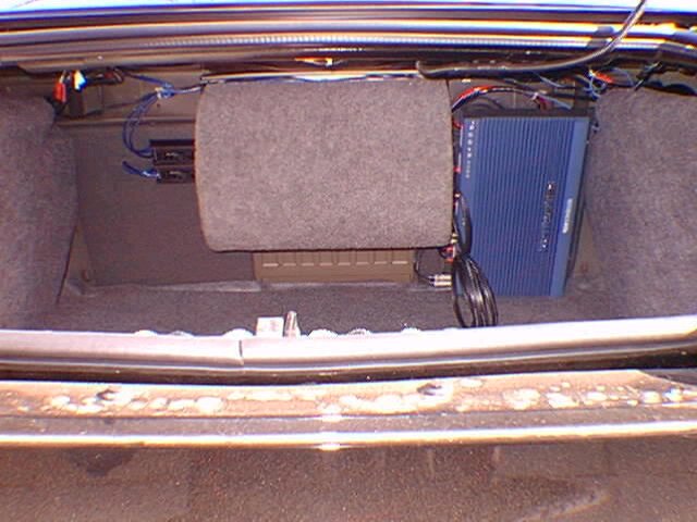
The wires near
the top usually don't show, they're really far back and under the
rear deck. Man, what a difference over the stock system. This was
a long and tedious process but well worth it! If anybody cares, I
spent two very full days doing the install (about 20 hours). This
was preceded with another 5 - 8 hours in the shop building
cables, making the panels and platform, and covering them with
carpet.
If you have
comments or questions about anything on this page, please read
the follow-up pages:
Audio Follow-Up #1
Audio
Follow-Up #2
Audio
Follow-Up #3
Audio
Follow-Up #4
Audio
Follow-Up #5
Audio
Follow-Up #6
Audio
Follow-Up #7
and if your
questions are still not answered, e-mail John Tsimaras and ask!